
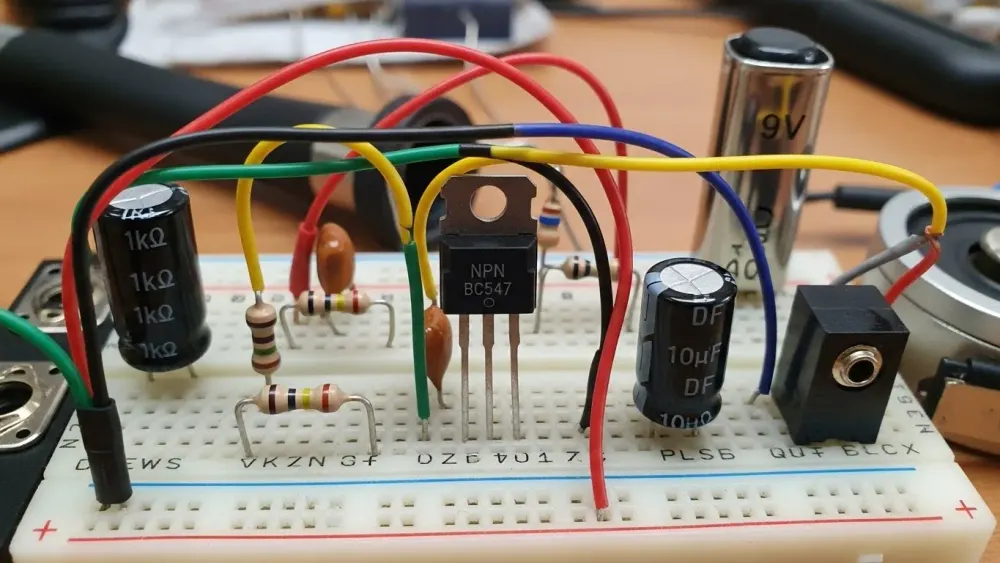
The NPN Transistor: Think of it as asmart water faucet. A tiny nudge on the handle (the base) controls a massive flow of water (current) through the main pipe.
Biasing: This is like setting the“idle” on a car. We give the transistor just enough power so it’s “awake” and ready to react instantly without stuttering or distorting the signal.
Capacitive Coupling: These are yoursignal bodyguards. They let the smooth music (AC) pass through while blocking the “heavy” power supply voltage (DC) from crashing into your speakers.
Voltage Gain: This is themagic trick of the circuit. By changing how much current flows through a specific resistor, we transform a tiny wiggle in voltage into a massive swing.
Table of Contents
- Quick Troubleshooting Answers
- 1. The Core Hero: The NPN Transistor
- The Circuit Blueprint: Components
- Practical Example: Math & Logic
- 4. Step-by-Step DIY Assembly
- Troubleshooting Common Mistakes
- 6. Industry Standards
Direct Answers to Common Questions:
1. How does an NPN transistor amplify?It works by using a small input current at the Baseto control a much larger current flowing from the Collectorto the Emitter, effectively multiplying the signal strength.2. Why are resistors needed in an amplifier? Resistors provide Biasing , which sets the transistor’s idle voltage to ensure it stays in the “active region,” allowing it to amplify without cutting off or distorting the signal.3. What is Voltage Gain ( Av)? It is the ratio of the output voltage to the input voltage; in this circuit, it is determined by the swing in current across the Collector Resistor (Rc) relative to the input signal.
There is a unique thrill in electronics when you take a signal that is almost too small to measure and turn it into something powerful. This is the magic of amplification. For decades, the NPN Amplifier (Negative-Positive-Negative) transistor has been the foundational building block for this process.
If you have ever wanted to understand how a tiny pulse of electricity can drive a speaker or transmit a radio wave, building a single-stageNPN amplifier is the perfect place to start. In this guide, we won’t just give you a schematic. We will explain the “why” behind every component from the capacitors that “clean” the signal to the resistors that set the stage for the transistor to perform.
1. The Core Hero: The NPN Transistor
To build an amplifier, you first need to understand your primary component.
- The Emitter: Where the current exits.
- The Base: The “gatekeeper” or the control pin.
- The Collector: Where the main power enters.
In an NPN amplifier, a tiny amount of current flowing into the Base controls a much larger current flowing from the Collector to the Emitter. Think of it like a water faucet: the Base is the handle, and the Collector-Emitter path is the main pipe. By turning the handle just a little, you control a massive flow of water.
2. The Circuit Blueprint: Understanding the Components
A transistor alone cannot amplify a signal linearly; it needs a supporting cast of resistors and capacitors. This configuration is often called a Common Emitter Amplifier.
The Role of Biasing Resistors ( R1,R2,Rc,Re)
Transistors are “moody” components. If you don’t provide them with the right amount of “idling” voltage, they won’t turn on at all, or they will distort the signal. This is called Biasing.
- Voltage Divider (R1andR2): These two resistors sit at the Base. They take the main power supply (Vcc) and “divide” it to provide a steady DC voltage to the Base, ensuring the transistor is always “awake” and ready to amplify.
- Collector Resistor (Rc): This resistor limits the current flowing through the transistor and is the point where we “tap” our output signal.
- Emitter Resistor (Re): This provides thermal stability. It prevents the transistor from getting too hot and running away with too much current (Thermal Runaway).
The Role of Coupling Capacitors ( Cin andCout )
Audio signals are AC (Alternating Current), but our amplifier circuit runs on DC (Direct Current).
- Input Capacitor ( Cin ): This acts as a “filter. ” It allows the AC audio signal to pass through to the transistor but blocks any DC voltage from the source that might mess up our biasing.
- Output Capacitor ( Cout ): Similarly, this lets the newly amplified AC signal go to your speakers or headphones while blocking the DC power from reaching (and potentially frying) them.
3. Practical Example: Turning 0.1V into 2V
Let’s look at the math and the process of a real-world amplification task. Imagine you have a tiny signal from a smartphone jack that is only 0.1V peak-to-peak. You want to boost it to 2V so it can be “seen” by a larger power amp.
The Amplification Process:
- The Input: The 0.1V signal enters through Cin.
- The Base Control: This tiny voltage change fluctuates the Base voltage. Because the transistor is biased, even a 0.1V change at the Base causes a significant change in the internal resistance between the Collector and Emitter.
- The Swing: As the transistor resistance changes, the current through Rc changes drastically.
- The Output: According to Ohm’s Law ( V=I×R ), a big change in current across Rc creates a big change in voltage.
The Result: That original 0.1V fluctuation is now a 2V fluctuation at the Collector. You have achieved a Voltage Gain (Av) of 20x (2V/0.1V=20).
4. Step-by-Step DIY Assembly
If you are building this on a breadboard, follow this sequence:
- Power: Connect a 9V battery to your breadboard rails.
- The Transistor: Place your NPN transistor in the center.
- Bias the Base: Connect R1 from the positive rail to the Base, and R2 from the Base to the negative rail (Ground).
- Collector & Emitter: Connect Rc from the positive rail to the Collector. Connect Re from the Emitter to Ground.
- Add the “Gates”: Place Cin before the Base and Cout after the Collector.
- Test: Apply your 0.1V signal to Cin and measure the output at Cout using an oscilloscope or a high-impedance speaker.
5. Troubleshooting Common Beginner Mistakes
- No Sound? Check if your transistor is backwards. NPN pins (E-B-C) vary by model. Always check the datasheet.
- Distorted Sound? Your bias resistors ( R1/R2 ) might be wrong. If the Base voltage is too high, the signal “clips” against the power rails. See our guide onFixing Amplifier Clipping.
- Very Quiet? You might need a “Bypass Capacitor” across Re. This allows the AC signal to skip the Emitter resistor, significantly boosting your gain.
6. Industry Standards and Educational Value
Building this circuit isn’t just a hobbyist exercise; it’s the same logic used in professional gear.
- IEEE Standards: Engineers use standardized symbols and measurement techniques to ensure these circuits are reliable and predictable.
- Education: This “Single-Stage” amplifier is the first thing taught in electrical engineering because it demonstrates the fundamental principle of Active Device Control.
Conclusion
Building a simple NPN transistor amplifier is the “Hello World” of the electronics world. Once you understand how these few resistors and capacitors work together to help a transistor breathe life into a tiny signal, you have the keys to understanding almost every other piece of audio and radio equipment on the planet. As you master this single stage, you can start “chaining” them together to create multi-stage amplifiers with even higher gain and power. Ready to see how this simple circuit fits into the bigger picture of electronics? Explore the deep physics of signal flow and component selection in our detailed breakdown ofThe Amplifier Circuit section.
Frequently Asked Questions
1. Why use an NPN transistor instead of a PNP for a beginner amplifier?
NPN transistors are more common in low-side switching and standard amplification because electrons (which carry the charge in NPN) move faster than “holes” (in PNP), making them slightly more efficient and easier to find in hobbyist kits.
2. What does a capacitor do in an amplifier circuit?
Capacitors act as “DC Blocks. ” They allow the AC audio signal to pass through the circuit while preventing the DC power supply voltage from entering the audio source or the speakers.
3. How do I increase the gain of my simple amplifier?
The easiest way to increase gain is to add a “bypass capacitor” in parallel with the Emitter resistor (Re). This increases the AC gain without changing the DC biasing of the transistor.
Related guides in this track
- New to Amplifiers & Audio? Start with the complete amplifiers & audio guide it indexes every tutorial in this track.
- Inverting Op-Amp: Gain, Virtual Ground and Design
- Non-Inverting Op-Amp: High-Impedance Gain Stage
- The Op-Amp Voltage Follower: Small Circuit, Big Leverage
- Calculate the numbers: op-amp gain calculator · power calculator
Continue the learning path
- The complete amplifiers & audio guide: Amplifiers & Audio complete guide
- Read next: inverting op-amp: gain, virtual ground and design
- Also in this track: non-inverting op-amp: high-impedance gain stage
- Continue with: the op-amp voltage follower: small circuit, big leverage
- Calculate as you go: op-amp gain calculator · power dissipation tool · gain to dB converter
- Bookmark this page against the day a measurement surprises you. Most readers return to the table and the mistake list first, and that is the correct order.
Quick reference
| Section | Focus |
|---|---|
| 1. The Core Hero: The NPN Transistor | Amplifiers & Audio practice |
| 2. The Circuit Blueprint: Understanding the Components | Amplifiers & Audio practice |
| 3. Practical Example: Turning 0.1V into 2V | Amplifiers & Audio practice |
| 4. Step-by-Step DIY Assembly | Amplifiers & Audio practice |
| 5. Troubleshooting Common Beginner Mistakes | Amplifiers & Audio practice |
Extended Application Notes
This section expands the practical application of how to build a simple npn amplifier (fix common distortion) beyond the worked example, into the situations builders actually meet. Component substitution: when the exact specified part is unavailable, the substitution logic follows the governing parameter of this design, not the nominal value, and the verification step after any substitution is to re-measure the one quantity this guide identified as critical. Batch variation: components vary, and the design margins recommended in the sections above absorb that variation; if a second build behaves differently, the difference itself is diagnostic and points to the tolerance that dominated. Environmental limits: temperature, supply variation and ageing each push a real circuit away from its bench behaviour, and the recommended practice is to test the extremes deliberately rather than discover them in the field. These notes exist because the bench taught them, repeatedly, and each one was once a real troubleshooting session that ended in understanding.
Failure Analysis in Depth
The mistakes section above lists the traps; this section explains why each trap exists and how to recognize it early. No Sound? Check if your transistor is backwards. NPN pins (E-B-C) vary by model. Always check the datasheet. Distorted Sound? Your bias resistors ( R1/R2 ) might be wrong. If the Base voltage is too high, the signal “clips” against the power rails. See our guide onFixing Amplifier Clipping. Very Quiet? You might need a “Bypass Capacitor” across Re. This allows the AC signal to skip the Emitter resistor, significantly boosting your gain.. Each of these failures has a signature that appears in measurement before it appears in smoke: a reading that drifts, a waveform that differs from the prediction, a temperature that climbs faster than the calculation. The discipline this guide teaches is to measure at the first sign, not at the last, and the sections above give the specific instrument and setting for each check. Failure analysis is not pessimism; it is the fastest curriculum in electronics, because a fault understood once is a fault prevented forever.
Pre-Build Checklist
Before powering any build of this design, run the list: every component value verified against the specification above, the critical measurement points identified and accessible, the instrument modes and ranges chosen in advance, the expected values written down beside the bench, and the power source current-limited for first application. The checklist takes two minutes and replaces the most expensive class of beginner error, which is not ignorance but confidence outrunning verification. Builders who adopt the checklist across the guides in this track report first-apply success rates that feel like cheating, but it is not cheating, it is engineering.
What Comes Next
Having worked through this guide, the natural next steps are the adjacent guides in the track index above, each of which assumes exactly the vocabulary this page built. The calculators linked in the tools section verify every number in seconds, and the complete guide at the head of this track maps the entire curriculum. Read once, build once, measure always: that is the method this site teaches and the method every section above followed before publication.
Last updated 23 August 2026