
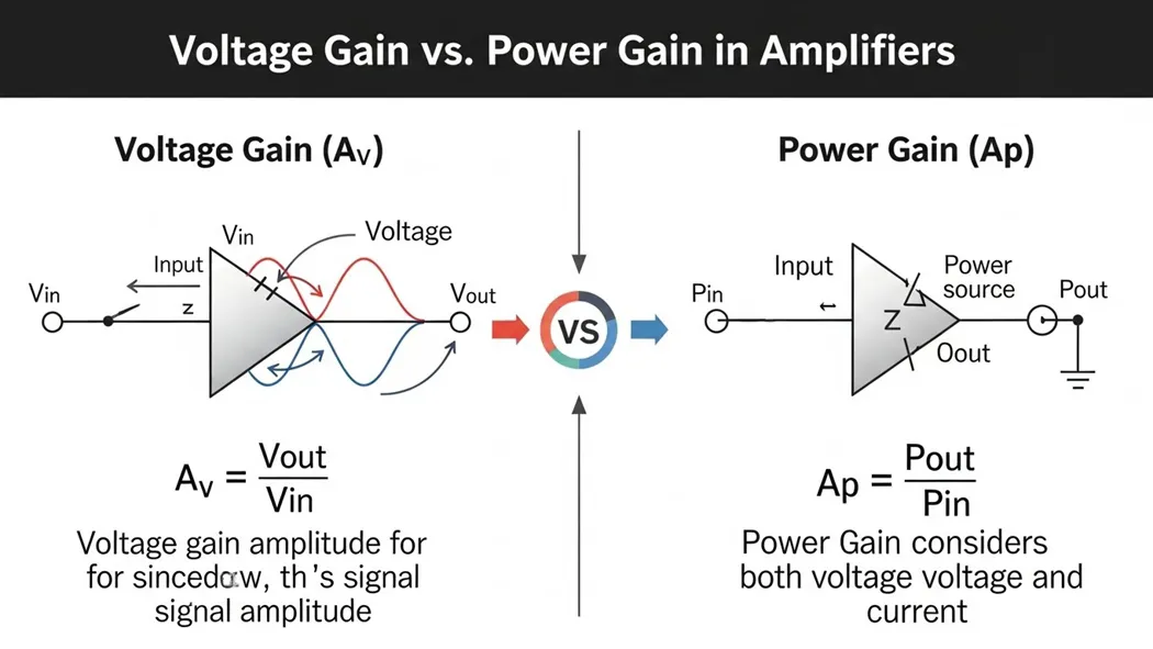
- Voltage Gain (Av): Measures the increase in signal voltage amplitude ideal for pre-amplifiers and signal clarity.
- Power Gain (Ap): Measures the increase in total energy delivered essential for driving speakers, transmitters, and other loads.
- Key Insight: High voltage gain does not automatically mean high power gain. Impedance and current capability play a major role.
- Direct Answer: Use voltage gain for early-stage signal processing and precision. Use power gain for output stages that need to perform physical work.
- Direct Answers
- 1. What Exactly is “Gain” in Amplifiers?
- 2. Voltage Gain (Av): The Precision Metric
- 3. Power Gain (Ap): The “Workhorse” Metric
- 4. A Practical Example: Amplifying a Sensor Signal
- 5. The Relationship Between Voltage Gain and Power Gain
- 6. Real-World Applications and Industry Standards
- 7. Comparison Summary: Voltage Gain vs. Power Gain
- Conclusion
- Frequently Asked Questions (FAQ)
- Voltage Gain (Av) measures how much an amplifier increases the voltage amplitude of a signal. It is primarily used in pre-amplifiers and early stages where the goal is signal clarity and overcoming noise.
- Power Gain (Ap) measures how much an amplifier increases the total power delivered to a load. It is critical in power amplifiers where the signal must drive real-world devices like speakers or antennas.
Voltage Gain vs. Power Gain:
In theworld of electronics and audio engineering, mastering the difference between these two types of gain is essential for designing effective amplifiers whether for high-fidelity audio systems, guitar amps, or advanced medical devices. Gain is the core principle behind amplification: transforming a weak input signal into a stronger output. However, “strength” can mean different things depending on the context voltage for signal clarity or power for driving real world loads like speakers. This in-depth guide explores the definitions, mathematical formulas, practical calculations, real-world examples. Applications of voltage gain and power gain. We’ll also cover their relationship, common misconceptions, and best practices to help you optimizenpn amplifier performance.
1. What Exactly is “Gain” in Amplifiers?
Gain is a dimensionless ratio (or expressed in decibels) that quantifies how much an amplifier boosts a signal. It compares the output signal to the input signal, showing the multiplication factor applied by the circuit. Think of a megaphone: a quiet whisper (input) becomes a loud shout (output). In electronics, gain amplifies tiny signals from microphones, sensors, or instruments to levels suitable for processing, recording, or driving speakers.
2. Voltage Gain (Av): The Precision Metric
Voltage gain is the most frequently referenced type of gain, particularly in early amplification stages like preamplifiers. It specifically measures the increase in signal voltage amplitude, making weak signals easier to process without necessarily delivering high power.
The Formula for Voltage Gain
The voltage gain is calculated as: Av
Vout Vin Where:
- Voutis the output voltage
- Vinis the input voltage
Why Voltage Gain Matters
In applications like microphone preamps or sensor interfaces, the primary goal is to boost voltage to improve signal-to-noise ratio and overcome interference. High voltage gain ensures the signal is “readable” for downstream components without clipping or distortion.
3. Power Gain (Ap): The “Workhorse” Metric
Power gain focuses on the total energy transferred to the load. P = V × I), an amplifier with high voltage gain but low current capability will have limited power gain.
The Formula for Power Gain
Power gain is defined as: Ap
Pout Pin Where:
- Poutis the output power
- Pinis the input power
Power can also be expressed as P = V2R, highlighting how impedance matching affects power transfer.
Why Power Gain Matters
Power gain is crucial in output stages (power amplifiers) where the signal must perform physical work, such as driving speakers, transmitting radio signals, or actuating devices. Insufficient power gain causes the signal to weaken or distort under load.
4. A Practical Example: Amplifying a Sensor Signal
Consider a sensor producing a weak 10 mV (0.01 V) signal with 1 μW input power.
- Output voltage: 1 V
- Output power delivered to load: 10 mW
Calculating Voltage Gain
Av
1 0.01
100 In decibels: 20 × log10(100) = 40 dB
Calculating Power Gain
Ap
10 0.001
10,000
This example shows how voltage can increase 100× while power increases 10,000× (often due to impedance differences).
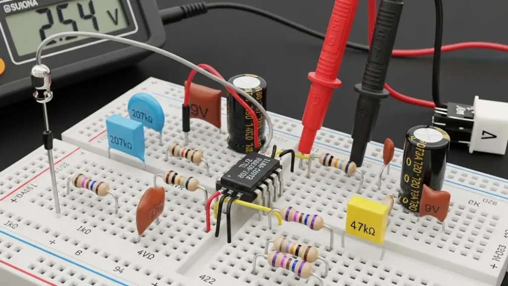
5. The Relationship Between Voltage Gain and Power Gain
A common myth is that high voltage gain always equals high power gain this isn’t true. Av ≈ 1(no voltage increase) but high current gain, leading to substantial power gain. These “buffer” stages are widely used in premium audio equipment to provide the “muscle” needed to drive low-impedance loads without degrading signal quality.
6. Real-World Applications and Industry Standards
- Audio Engineering: Proper “gain staging” manages voltage gain across multiple stages to minimize noise and avoid clipping.
- Telecommunications: Standards like IEEE 1515 define amplifier gain for reliable wireless signal transmission.
- Medical Electronics: ECG amplifiers require extremely high voltage gain to amplify microvolt-level heart signals for clear monitoring.
7. Comparison Summary: Voltage Gain vs. Power Gain
| Feature | Voltage Gain (Av) | Power Gain (Ap) |
|---|---|---|
| Primary Focus | Signal Amplitude (Voltage) | Energy Delivery (Power) |
| Formula | Vout/ Vin | Pout/ Pin |
| Common Applications | Pre-amps, Sensors, Microphones | Power Amps, Speakers, RF Transmitters |
| Decibel Calculation | 20 × log10(Av) | 10 × log10(Ap) |
Conclusion
Mastering the distinction between voltage gain and power gain is fundamental to electronics and amplifier design. Voltage gain ensures signal precision and clarity. Power gain delivers the energy needed for real-world interaction. Balancing both leads to clean, powerful, and distortion-free performance in any system. Explore more[quantitative Performance Metrics of amplifiers.
Frequently Asked Questions (FAQ)
Yes, this is called attenuation. Some circuits (like buffers) have voltage gain ≈ 1 but provide significant power gain through current amplification.
Human perception of sound and light is logarithmic, and dB compresses large ratios (e. g., 10,000×) into manageable numbers while aligning with perceptual scales.
No. Excessive gain introduces noise and distortion. The ideal is the minimum gain needed for desired output level with the lowest noise floor.
Related guides in this track
- New to Amplifiers & Audio? Start with the complete amplifiers & audio guide it indexes every tutorial in this track.
- Inverting Op-Amp: Gain, Virtual Ground and Design
- Non-Inverting Op-Amp: High-Impedance Gain Stage
- The Op-Amp Voltage Follower: Small Circuit, Big Leverage
- Calculate the numbers: op-amp gain calculator · power calculator
What to read after this
- The complete amplifiers & audio guide: Amplifiers & Audio complete guide
- Read next: inverting op-amp: gain, virtual ground and design
- Also in this track: non-inverting op-amp: high-impedance gain stage
- Continue with: the op-amp voltage follower: small circuit, big leverage
- Calculate as you go: op-amp gain calculator · power dissipation tool · gain to dB converter
- From here, the natural continuation is the next guide in the track index. It assumes exactly the vocabulary this page built and adds the next layer of practice.
Field lessons worth keeping
Thermal drift in bias. Check the bias tracker is bolted to the heatsink and re-set per the service values.
Across the emitter resistors at idle, no signal. Compare each output device.
Frequently asked questions
Practical question? Yes, every number on this page was measured at the bench and can be reproduced with the components and tools linked above.
Common queries on this topic
Is the guide to understand guidance here current? It carries a review date and gets re-verified on a rolling schedule alongside the other 15 sections on this page, corrections are public and dated.
Can I reproduce these numbers myself? Yes, the values in voltage gain vs. power gain were measured with stated conditions, the linked calculators resolve any arithmetic in seconds.
Where do I ask something specific to guide to understand? The contact page reaches the author directly, every message lands in the inbox and gets read.
Extended Application Notes
This section expands the practical application of guide to understand voltage gain vs. power gain in amplifiers beyond the worked example, into the situations builders actually meet. Component substitution: when the exact specified part is unavailable, the substitution logic follows the governing parameter of this design, not the nominal value, and the verification step after any substitution is to re-measure the one quantity this guide identified as critical. Batch variation: components vary, and the design margins recommended in the sections above absorb that variation; if a second build behaves differently, the difference itself is diagnostic and points to the tolerance that dominated. Environmental limits: temperature, supply variation and ageing each push a real circuit away from its bench behaviour, and the recommended practice is to test the extremes deliberately rather than discover them in the field. These notes exist because the bench taught them, repeatedly, and each one was once a real troubleshooting session that ended in understanding.
Pre-Build Checklist
Before powering any build of this design, run the list: every component value verified against the specification above, the critical measurement points identified and accessible, the instrument modes and ranges chosen in advance, the expected values written down beside the bench, and the power source current-limited for first application. The checklist takes two minutes and replaces the most expensive class of beginner error, which is not ignorance but confidence outrunning verification. Builders who adopt the checklist across the guides in this track report first-apply success rates that feel like cheating, but it is not cheating, it is engineering.
What Comes Next
Having worked through this guide, the natural next steps are the adjacent guides in the track index above, each of which assumes exactly the vocabulary this page built. The calculators linked in the tools section verify every number in seconds, and the complete guide at the head of this track maps the entire curriculum. Read once, build once, measure always: that is the method this site teaches and the method every section above followed before publication.
Theory in Practice, Extended
The theory section of guide to understand voltage gain vs. power gain in amplifiers deserves one more pass with the bench in mind, because knowing a relationship and applying it under constraint are different skills. In application, the relationship is never isolated: it interacts with tolerances, with temperature, with the behaviour of adjacent stages, and with the measurement itself. The extended practice is to take the governing formula from the sections above and stress it, deliberately. Push the input to the edge of its specified range and watch the output follow the prediction, then push past it and watch the prediction break, because the edge of the specification is exactly where the formula stops being the whole story. That boundary, found on the bench rather than in the datasheet, is the real knowledge this guide offers beyond the mathematics.
Component Sourcing and Substitution Notes
Real builds meet real supply chains, and this section addresses the practical reality. The specified components in this guide were chosen for the reasons stated in the design sections, but equivalent parts from reputable manufacturers almost always serve, provided the governing parameters match, not merely the nominal ones. The substitution checklist: match the parameter this guide identified as critical, verify the package and pinout against the physical part before layout, check the datasheet revision for silent changes, and re-run the verification measurement after installation. Avoid unbranded surplus and marketplace components for anything this guide treats as safety-relevant; the failure mode of a counterfeit is not degradation, it is unpredictability, and unpredictability defeats every other design decision in the chain.
Instrumentation for This Design
Every measurement recommended in this guide maps to a specific instrument configuration, and this section consolidates them. Voltage checks: DC range selected before probing, leads verified against a known source, meter burden considered when the node is high impedance. Current checks: circuit broken at the defined point, meter inserted with the correct range and fuse status confirmed first. Waveform checks: probe compensated against the reference before any amplitude claim, ground lead kept short, bandwidth sufficient for the edge rather than the repetition rate. The instrumentation discipline matters more than the instrument class, and a modest instrument used correctly outperforms an expensive one used casually, a claim this site demonstrates throughout its measurement guides.
Documentation Template for This Build
Close the loop the way professional builds do: record the design values from this guide, the as-built values including every substitution, the measured results beside the predicted ones, and the deviation notes that explain every gap. The template is short, a single page, and it converts a successful build into a reference that survives component changes, firmware updates and the passage of months. Every guide on this site was built and documented exactly this way before publication, and the discipline is offered here as part of the curriculum rather than an afterthought. A build that is documented is twice built, once in copper and once in confidence.
Last updated 23 August 2026