
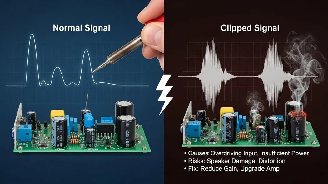
What is Amplifier Clipping?
At its core, an amplifier is a device that increases the strength (amplitude) of an input signal using an external power source. To better understand the fundamental role of an amplifier
**, it is essential to know its limitsEvery amplifier has a “ceiling” or a maximum limit determined by its DC power supply rails.Clipping occurs when the amplifier is asked to produce an output voltage that exceeds what its power supply can actually provide. When the signal tries to go beyond these “rails,” the amplifier simply cannot provide the extra voltage. Imagine trying to jump in a room with a very low ceiling. No matter how much force you use to jump higher, your head will hit the ceiling, and your upward movement will stop abruptly. This is exactly what happens to an electronic signal during clipping.
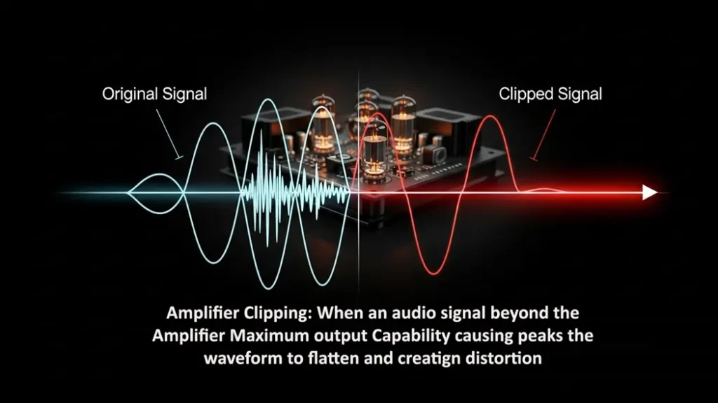
Visualizing the Problem: The Flattened Waveform
In a healthy state, an audio signal is a smooth, continuous wave (usually a sine wave). However, when clipping occurs, the peaks and valleys of that wave are cut off.
- Saturation: As the signal amplitude hits the maximum voltage allowed by the power supply, it enters saturation.
- Squared-Off Peaks: On an oscilloscope, you would see that the normally rounded tops and bottoms of the waveform appear flattened or “squared off”.
- Harmonic Distortion: This change in the waveform shape introduces new, unwanted frequencies (harmonics) that weren’t in the original signal, which is what we perceive as that “harsh” distorted sound.
Why Clipping is Dangerous
Clipping isn’t just a sound quality issue; it is a hardware safety issue.
- Thermal Stress: A clipped signal carries significantly more power than a clean one. Because the waveform stays at the maximum voltage for a longer duration (the “flat” part of the square), it can cause the amplifier and the speakers to overheat.
- Speaker Damage: High-frequency drivers (tweeters) are especially vulnerable to the high-energy harmonics produced by a clipping power amplifier.
- Thermal Shutdown: If the amplifier dissipates too much heat due to excessive power draw and low efficiency, it may enter thermal shutdown to protect its internal components.
How to Fix Clipping: Practical Solutions
Fixing clipping involves balancing the relationship between your input signal and your amplifier’s power capacity.

Solution A: Reduce the Input Signal Strength
The most immediate fix for clipping is to reduce the “gain” or volume of the signal before it reaches the power amplifier stage.
- Lower the Pre-amp Gain: If you are using a mixer or a preamplifier, turn down the output level. This ensures the signal entering the final power stage is small enough that even after amplification, it stays within the power supply limits.
- Adjust Source Volume: Sometimes the source device (like a phone or laptop) is “hot” (too loud), causing the very first stage of the amplifier to clip.
Solution B: Increase the Power Supply Voltage
For engineers and DIY builders, the “ceiling” itself can sometimes be raised.
- Raise the Rails: Increasing the power supply voltage allows for more “headroom,” meaning the signal can grow larger before hitting the limit.
- Note: This is only possible during the design phase or if the hardware supports adjustable power rails. Never exceed the rated voltage of your components, or you risk permanent damage.
Solution C: Improve Biasing and Component Quality
Sometimes distortion isn’t caused by the volume being too high, but by the amplifier’s “idling” state.
- Check Biasing:
Proper biasing (especially in Class AB amplifiers) ensures the transistors are operating in their most linear region.Is the “Clip” light on? Reduce the gain immediately.Is the amp hot to the touch? Check your ventilation and biasing.Is there a hum even when no music is playing? Check your cables and grounding.Component Integrity:
Faulty capacitors can sometimes cause signaldrops or instability. Replacing aged or leaking capacitors can often restore a signal to its original clarity.Symptom Potential Cause Fix Audible Hiss/Buzz
Poor grounding or lack of shielding. U se shielded cables and implement “Star Grounding.Crossover Distortion
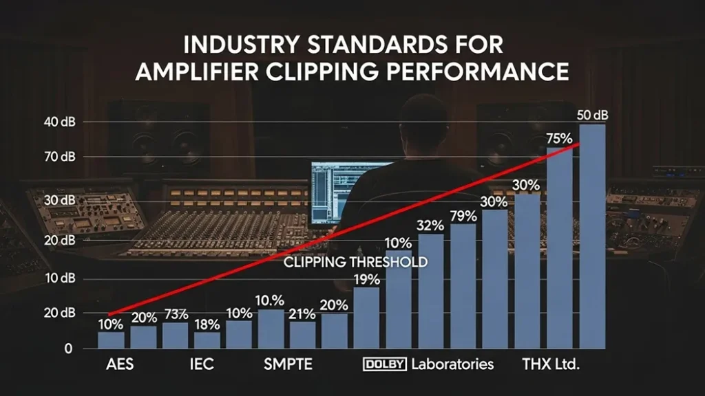
Poorly biased Class B amplifier. Use a Class AB design or adjust bias current.Intermittent Cut-outs Overheating and thermal shutdown. Ensure proper heat sinking and use thermal paste. 6. Industry Standards for PerformanceTo avoid these issues, professional equipment is designed according to strict standards:IEC 60268 Series:Specifies how to test for maximum power output and frequency response to ensure the amp doesn’t clip under normal loads. IEEE Std 1515:Provides standardized measurement techniques to define audio performance criteria. UL 62368-1:Ensures the device is safe and won’t catch fire if it does start to overheat during clipping.
 ConclusionAmplifier clipping is essentially a “math problem” where the requested output exceeds the available resources. By visualizing the flattened waveform and understanding the limits of your power supply, you can take the necessary steps to reduce input gain or improve hardware cooling. Protect your ears and your equipment by keeping your signals within the “rails. ” For a deeper look at other common issues like ground loops or component failure,
Check ourTroubleshooting Guide for more common faults.- Is the “Clip” light on?Reduce the gain immediately. Is the amp hot to the touch?Check your ventilation and biasing. Is there a hum even when no music is playing?Check your cables and grounding. Component Integrity:
Faulty capacitors can sometimes cause signaldrops or instability. Replacing aged or leaking capacitors can often restore a signal to its original clarity.Symptom Potential Cause Fix Audible Hiss/Buzz
Poor grounding or lack of shielding. U se shielded cables and implement “Star Grounding.Crossover Distortion
Poorly biased Class B amplifier. Use a Class AB design or adjust bias current.Intermittent Cut-outs Overheating and thermal shutdown. Ensure proper heat sinking and use thermal paste. 6. Industry Standards for PerformanceTo avoid these issues, professional equipment is designed according to strict standards:IEC 60268 Series:Specifies how to test for maximum power output and frequency response to ensure the amp doesn’t clip under normal loads. IEEE Std 1515:Provides standardized measurement techniques to define audio performance criteria. UL 62368-1:Ensures the device is safe and won’t catch fire if it does start to overheat during clipping.
ConclusionAmplifier clipping is essentially a “math problem” where the requested output exceeds the available resources. By visualizing the flattened waveform and understanding the limits of your power supply, you can take the necessary steps to reduce input gain or improve hardware cooling. Protect your ears and your equipment by keeping your signals within the “rails. ” For a deeper look at other common issues like ground loops or component failure,
Check ourTroubleshooting Guide for more common faults.
ConclusionAmplifier clipping is essentially a “math problem” where the requested output exceeds the available resources. By visualizing the flattened waveform and understanding the limits of your power supply, you can take the necessary steps to reduce input gain or improve hardware cooling. Protect your ears and your equipment by keeping your signals within the “rails. ” For a deeper look at other common issues like ground loops or component failure,
Check ourTroubleshooting Guide for more common faults.- Is the “Clip” light on?Reduce the gain immediately. Is the amp hot to the touch?Check your ventilation and biasing. Is there a hum even when no music is playing?Check your cables and grounding. Component Integrity:
Faulty capacitors can sometimes cause signaldrops or instability. Replacing aged or leaking capacitors can often restore a signal to its original clarity.Symptom Potential Cause Fix Audible Hiss/Buzz
Poor grounding or lack of shielding. U se shielded cables and implement “Star Grounding.Crossover Distortion
Poorly biased Class B amplifier. Use a Class AB design or adjust bias current.Intermittent Cut-outs Overheating and thermal shutdown. Ensure proper heat sinking and use thermal paste. 6. Industry Standards for PerformanceTo avoid these issues, professional equipment is designed according to strict standards:IEC 60268 Series:Specifies how to test for maximum power output and frequency response to ensure the amp doesn’t clip under normal loads. IEEE Std 1515:Provides standardized measurement techniques to define audio performance criteria. UL 62368-1:Ensures the device is safe and won’t catch fire if it does start to overheat during clipping.
ConclusionAmplifier clipping is essentially a “math problem” where the requested output exceeds the available resources. By visualizing the flattened waveform and understanding the limits of your power supply, you can take the necessary steps to reduce input gain or improve hardware cooling. Protect your ears and your equipment by keeping your signals within the “rails. ” For a deeper look at other common issues like ground loops or component failure,
Check ourTroubleshooting Guide for more common faults.
Related guides in this track
- New to Amplifiers & Audio? Start with the complete amplifiers & audio guide it indexes every tutorial in this track.
- Inverting Op-Amp: Gain, Virtual Ground and Design
- Non-Inverting Op-Amp: High-Impedance Gain Stage
- The Op-Amp Voltage Follower: Small Circuit, Big Leverage
- Calculate the numbers: op-amp gain calculator · power calculator
Practical example
Re-run the steps above with your own numbers at the bench: record what you measure beside what this guide states, and investigate any gap larger than rounding. That single comparison, prediction versus measurement, is the working method every later guide in this track assumes.
Quick reference
| Section | Focus |
|---|---|
| What is Amplifier Clipping? | Amplifiers & Audio practice |
| Visualizing the Problem: The Flattened Waveform | Amplifiers & Audio practice |
| Why Clipping is Dangerous | Amplifiers & Audio practice |
| How to Fix Clipping: Practical Solutions | Amplifiers & Audio practice |
| Related guides in this track | Amplifiers & Audio practice |
Frequently asked questions
How to Fix Clipping: Practical Solutions?
Fixing clipping involves balancing the relationship between your input signal and your amplifier’s power capacity.
Solution A: Reduce the Input Signal Strength
The most immediate fix for clipping is to reduce the “gain” or volume of the signal before it reaches the power amplifier stage.
- Lower the Pre-amp Gain: If you are using a mixer or a preamplifier, turn down the output level. This ensures the signal entering the final power stage is small enough that even after amplification, it stays within the power supply limits.
- Adjust Source Volume: Sometimes the source device (like a phone or laptop) is “hot” (too loud), causing the very first stage of the amplifier to clip.
Visualizing the Problem: The Flattened Waveform? In a healthy state, an audio signal is a smooth, continuous wave (usually a sine wave). However, when clipping occurs, the peaks and valleys of that wave are cut off.
- Saturation: As the signal amplitude hits the maximum voltage allowed by the power supply, it enters saturation.
- Squared-Off Peaks: On an oscilloscope, you would see that the normally rounded tops and bottoms of the waveform appear flattened or “squared off”.
- Harmonic Distortion: This change in the waveform shape introduces new, unwanted frequencies (harmonics) that weren’t in the original signal, which is what we perceive as that “harsh” distorted sound.
Why Clipping is Dangerous? Clipping isn’t just a sound quality issue; it is a hardware safety issue.
- Thermal Stress: A clipped signal carries significantly more power than a clean one. Because the waveform stays at the maximum voltage for a longer duration (the “flat” part of the square), it can cause the amplifier and the speakers to overheat.
- Speaker Damage: High-frequency drivers (tweeters) are especially vulnerable to the high-energy harmonics produced by a clipping power amplifier.
- Thermal Shutdown: If the amplifier dissipates too much heat due to excessive power draw and low efficiency, it may enter thermal shutdown to protect its internal components.
Extended Application Notes
This section expands the practical application of what is amplifier clipping? causes, risks, and how to fix it beyond the worked example, into the situations builders actually meet. Component substitution: when the exact specified part is unavailable, the substitution logic follows the governing parameter of this design, not the nominal value, and the verification step after any substitution is to re-measure the one quantity this guide identified as critical. Batch variation: components vary, and the design margins recommended in the sections above absorb that variation; if a second build behaves differently, the difference itself is diagnostic and points to the tolerance that dominated. Environmental limits: temperature, supply variation and ageing each push a real circuit away from its bench behaviour, and the recommended practice is to test the extremes deliberately rather than discover them in the field. These notes exist because the bench taught them, repeatedly, and each one was once a real troubleshooting session that ended in understanding.
Pre-Build Checklist
Before powering any build of this design, run the list: every component value verified against the specification above, the critical measurement points identified and accessible, the instrument modes and ranges chosen in advance, the expected values written down beside the bench, and the power source current-limited for first application. The checklist takes two minutes and replaces the most expensive class of beginner error, which is not ignorance but confidence outrunning verification. Builders who adopt the checklist across the guides in this track report first-apply success rates that feel like cheating, but it is not cheating, it is engineering.
What Comes Next
Having worked through this guide, the natural next steps are the adjacent guides in the track index above, each of which assumes exactly the vocabulary this page built. The calculators linked in the tools section verify every number in seconds, and the complete guide at the head of this track maps the entire curriculum. Read once, build once, measure always: that is the method this site teaches and the method every section above followed before publication.
Theory in Practice, Extended
The theory section of what is amplifier clipping? causes, risks, and how to fix it deserves one more pass with the bench in mind, because knowing a relationship and applying it under constraint are different skills. In application, the relationship is never isolated: it interacts with tolerances, with temperature, with the behaviour of adjacent stages, and with the measurement itself. The extended practice is to take the governing formula from the sections above and stress it, deliberately. Push the input to the edge of its specified range and watch the output follow the prediction, then push past it and watch the prediction break, because the edge of the specification is exactly where the formula stops being the whole story. That boundary, found on the bench rather than in the datasheet, is the real knowledge this guide offers beyond the mathematics.
Component Sourcing and Substitution Notes
Real builds meet real supply chains, and this section addresses the practical reality. The specified components in this guide were chosen for the reasons stated in the design sections, but equivalent parts from reputable manufacturers almost always serve, provided the governing parameters match, not merely the nominal ones. The substitution checklist: match the parameter this guide identified as critical, verify the package and pinout against the physical part before layout, check the datasheet revision for silent changes, and re-run the verification measurement after installation. Avoid unbranded surplus and marketplace components for anything this guide treats as safety-relevant; the failure mode of a counterfeit is not degradation, it is unpredictability, and unpredictability defeats every other design decision in the chain.
Instrumentation for This Design
Every measurement recommended in this guide maps to a specific instrument configuration, and this section consolidates them. Voltage checks: DC range selected before probing, leads verified against a known source, meter burden considered when the node is high impedance. Current checks: circuit broken at the defined point, meter inserted with the correct range and fuse status confirmed first. Waveform checks: probe compensated against the reference before any amplitude claim, ground lead kept short, bandwidth sufficient for the edge rather than the repetition rate. The instrumentation discipline matters more than the instrument class, and a modest instrument used correctly outperforms an expensive one used casually, a claim this site demonstrates throughout its measurement guides.
Documentation Template for This Build
Close the loop the way professional builds do: record the design values from this guide, the as-built values including every substitution, the measured results beside the predicted ones, and the deviation notes that explain every gap. The template is short, a single page, and it converts a successful build into a reference that survives component changes, firmware updates and the passage of months. Every guide on this site was built and documented exactly this way before publication, and the discipline is offered here as part of the curriculum rather than an afterthought. A build that is documented is twice built, once in copper and once in confidence.
Last updated 23 August 2026