
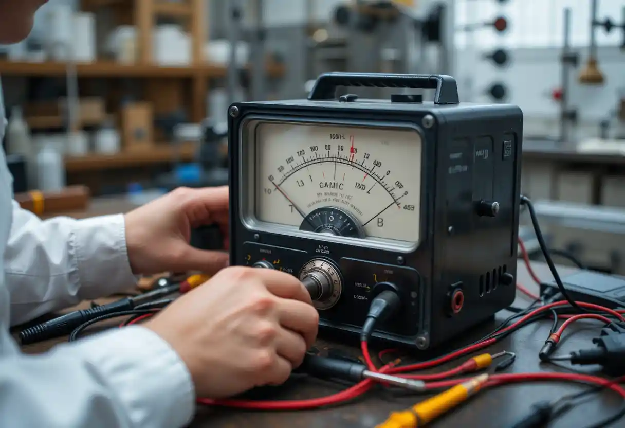
- Understanding Moving Iron Repulsion Type Instruments
- Step-by-Step Calibration Process
- Common Errors and Troubleshooting Tips
- Maintenance Best Practices
- Comparison with Digital Instruments
- Frequently Asked Questions Struggling with wonky readings from a panel ammeter? Maintaining the accuracy of MovingIron Repulsion Type Instruments is critical for safe industrial metering, especially given their susceptibility to mechanical wear and frequency error. This comprehensive guide equips technicians with the knowledge to eliminate common faults like pointer sticking and zero drift. You’ll master the calibration equation, interpret IEC accuracy classes, and apply advanced troubleshooting techniques to guarantee your rugged MI meters provide reliable$\mathbf{RMS \text{ measurements}}$in any environment.
Comparative Analysis: Moving Iron (MI) vs. Permanent Magnet Moving Coil (PMMC)
Selecting the right analog meter depends on the power source being measured AC or DC.
| Feature | Moving Iron (MI) | Moving Coil (PMMC) |
|---|---|---|
| Operating Principle | Repulsion between two iron vanes (based on $I^2$). | Force on a current-carrying conductor in a fixed magnetic field ($\propto I$). |
| Measurement Type | AC and DC (measures RMS for AC). | DC Only(or AC rectified, but intrinsically DC). |
| Accuracy Class | Lower (Typically Class 1.0 to 2.5). | Higher (Typically Class 0.5 to 1.0). |
| Scale Linearity | Non-linear ($I^2$) and cramped at the start. | Perfectly linear ($I$). |
Understanding Moving Iron Repulsion Type Instruments
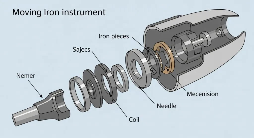
Moving iron repulsion type instruments measureelectrical current or voltage using the repulsion between two iron pieces in a magnetic field, which moves a needle across a scale. You’ll find them in power plants, industrial settings, or labs where accurate electrical measurements are crucial. Unlike digital meters, these instruments are rugged and handle both AC and DC without fancy electronics. But dust, wear, or improper handling can throw off their accuracy, so regular calibration and maintenance are key.
These devices shine in tough environments where durability matters more than high-tech features. Knowing how they work and how to care for them ensures they keep delivering reliable results.
The Physics of Repulsion: Formulas and Scale Non-Linearity
The operation of a moving iron instrument is governed by the electromagnetic torque ($T_d$) that deflects the pointer and the control torque ($T_c$) that opposes it. These formulas dictate the instrument’s non-linear scale.
1. Deflection Torque ($T_d$)
The torque is proportional to the square of the RMS current ($I$), making the instrument suitable for measuring AC signals.
$$T_d = \frac{1}{2} I^2 \frac{dL}{d\theta}$$
In simplified terms, the deflection torque is universally proportional to the square of the current:
$$T_d \propto I^2$$
2. Calibration Equation (Scale Factor)
Since the deflection ($\theta$) is proportional to $I^2$, the Scale Factor used during calibration relates the deflection to the square of the measured current:
$$\text{Scale Factor} = \frac{\text{Deflection ($\theta$)}}{\text{Current}^2 (I^2)}$$
Worked Example: If an instrument has a constant $K = 0.5 \text{ deg/A}^2$. If a current of $3 \text{ Amperes}$ is applied, the expected deflection is $\theta = K \cdot I^2 = 0.5 \cdot (3)^2 = \mathbf{4.5 \text{ degrees}}$. This non-linear relationship causes the scale to be cramped at the low end and spread out at the high end.
Step-by-Step Calibration Process
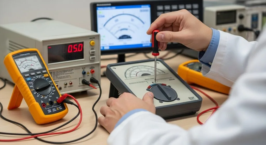
Calibrating a moving iron instrument keeps its readings accurate. Here’s a simple guide to do it right:
- Gather Your Tools: Grab a calibrated multimeter (as a reference standard), a stable power source, a small screwdriver, and a clean, static-free workspace. A variable resistor or load can help test different ranges.
- Inspect the Instrument: Look for physical damage, loose connections, or a stuck needle. Wipe the exterior with a soft cloth to clear dust that could affect internal parts.
- Set Up the Reference: Connect the instrument in series (for ammeters) or parallel (for voltmeters) with the reference multimeter. Ensure the power source matches the instrument’s range.
- Apply a Known Value: Start with a low, stable current or voltage within the instrument’s range. Compare its reading to the multimeter’s.
- Adjust the Zero Point: If the needle isn’t at zero with no input, use the zero-adjust screw (usually near the bottom) to align it. Turn gently to avoid overwinding.
- Fine-Tune the Scale: Apply known values across the range (e. g., 25%, 50%, 75%, 100%). If readings are off, adjust the calibration screws (often inside the casing) to match the reference. Repeat until accurate.
- Test and Verify: Run tests at multiple points to confirm consistency. Record results for future reference.
Calibration isn’t a one-time thing. Regular checks, especially in busy settings, keep your measurements trustworthy.
Quantified Case Studies: MI Instruments in Professional Environments
Case 1: Power Plant Control Room Monitoring
Moving iron ammeters are widely used on generator and feeder panels due to their ability to directly measure RMS current without complex internal electronics.
- Requirement: Instrument Class $1.5$ meters for monitoring feeder loads. This means the reading must be accurate to within $\pm 1.5%$ of the Full-Scale Deflection (FSD).
- Calibration Interval: Due to constant vibration and thermal cycling, the internal standard operating procedure (SOP) mandates a $\mathbf{6 \text{ month}}$ calibration interval, traceable to ISO/IEC 17025 standards.
Case 2: Industrial Metering and Reactive Power
MI instruments, especially wattmeters derived from MI principles, are used for measuring power on heavily inductive loads (motors, transformers).
- Design Challenge: The meter must be calibrated at a specified power frequency ($\mathbf{60 \text{ Hz}}$). If the instrument is used on a variable frequency drive (VFD) output, the coil’s inductive reactance ($\omega L$) will change, causing a significant frequency error ($\theta \propto I^2 / (R^2 + (\omega L)^2)$), rendering the measurement unreliable.
Case 3: Laboratory Calibration with Standard Sources
A calibration lab uses a high-precision, adjustable AC source as the reference.
- Procedure: A $10 \text{ A}$ MI meter is tested. The reference is set to $5 \text{ A}$. The MI meter reads $4.8 \text{ A}$. The $\mathbf{200 \text{ mA}}$ deviation is corrected by adjusting the internal scale factor mechanism until the reading matches the reference.
Common Errors and Troubleshooting Tips
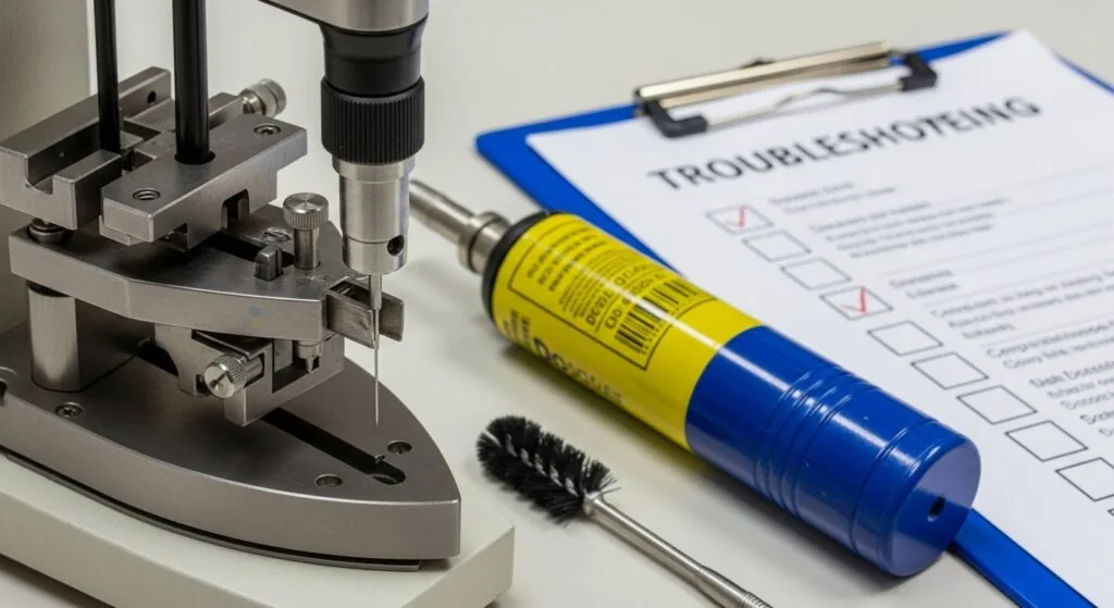
Even with careful calibration, issues can pop up. Here’s how to tackle common problems:
- Stuck Needle: Dust or debris can jam the mechanism. Gently tap the meter or use compressed air to clear it. If it’s still stuck, open the casing in a clean environment to check for obstructions.
- Inconsistent Readings: Loose connections or worn contacts might be to blame. Tighten terminals and check for corrosion. If the problem persists, the internal coil may need professional repair.
- Zero Drift: If the needle doesn’t return to zero, recalibrate the zero point. Ongoing drift could mean a weak spring or magnet, which may require replacement.
- Overloading Errors: Applying current or voltage beyond the instrument’s range can skew readings. Always verify the range before testing and use protective circuits if possible.
Advanced Troubleshooting: Common Issues and Fixes
Troubleshooting MI instruments requires addressing both mechanical wear (pivots, bearings) and electromagnetic errors (hysteresis, frequency).
| Symptom / Issue | Primary Cause / Error Type | Professional Fix |
|---|---|---|
| Pointer Sticking / Slow Movement | High Frictional Torque due to mechanical wear of pivots and jewel bearings. | Disassemble and inspect/replace pivots and bearings. Clean the damping mechanism with compressed air or solvent. |
| Inconsistent Readings (Ascending/Descending) | Hysteresis Error (residual magnetism in the iron vanes). | Degauss or demagnetize the iron vanes. Alternatively, recalibrate the instrument using the maximum current before taking measurements. |
| Reading Error Varies with Viewing Angle | Parallax Error (The pointer and its reflection are not aligned). | Ensure the instrument uses a mirror-backed scale and train the user to view the pointer perpendicularly (the pointer must cover its own reflection). |
Maintenance Best Practices
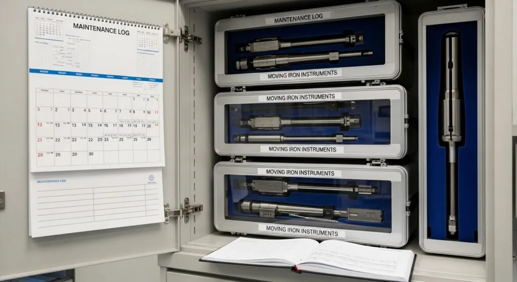
Regular maintenance keeps moving iron instruments reliable. Here’s how to do it:
- Weekly Checks: Inspect for dust, loose parts, or wear. Clean the exterior with a dry, lint-free cloth.
- Monthly Calibration: In high-use environments, calibrate monthly to catch drift early. In low-use settings, every 3-6 months works.
- Proper Storage: Store in a cool, dry place away from strong magnetic fields or vibrations. Use protective covers to keep dust out.
- Avoid Overloading: Check the instrument’s range before use. Overloading can damage the internal mechanism.
- Handle with Care: Avoid dropping or jarring the instrument, as its delicate parts are sensitive to shock.
These habits save time and prevent costly repairs, keeping your instruments ready for action.
Comparison with Digital Instruments
| Feature | Moving Iron Instruments | Digital Instruments |
|---|---|---|
| Measurement Type | AC and DC | Primarily DC, some AC models |
| Durability | High (rugged, no complex electronics) | Moderate (sensitive to damage) |
| Calibration Frequency | Monthly or quarterly | Less frequent (self-calibrating) |
| Accuracy | Good, but needs regular calibration | High, often self-correcting |
| Cost | Lower initial cost | Higher, due to advanced tech |
| Ease of Use | Simple, but needs manual calibration | User-friendly, automated features |
| Environmental Tolerance | Resilient to dust, vibration | Sensitive to extreme conditions |
This table shows why moving iron instruments are still valued in rugged settings, even with digital options available. Their durability and simplicity make them a go-to for many tasks.
Industry Standards: Compliance and Calibration Traceability
Accurate and reliable measurements are guaranteed only when MI instruments are selected and maintained according to international compliance standards.
1. Instrument Accuracy Classification
- IEC 60051: This international standard specifies requirements for Direct Acting Indicating Analogue Electrical Measuring Instruments (which includes MI meters). It defines testing methods and operational requirements.
- ANSI C39.1: The primary American national standard covering the requirements for electrical analog indicating instruments, including definitions for Accuracy Classes (e. g., $1.0, 1.5$).
2. Calibration and Metrological Traceability
- ISO/IEC 17025: This is the global benchmark for laboratory competence. For professional maintenance, the calibration lab must be $17025$-compliant, ensuring the measurement is traceable back to national and international standards (e. g., NIST, NMI).
- Calibration Intervals: While not fixed by standard, $17025$ dictates that the interval must be based on the instrument’s stability and usage. For MI instruments in industrial settings, a $\mathbf{3-6 \text{ month}}$ interval is generally recommended to prevent excessive drift due to mechanical wear and vibration.
Wrapping It Up
Calibrating and maintaining moving iron repulsion type instruments doesn’t have to be a headache. With a clear calibration process, quick fixes for common issues, and a solid maintenance routine, you can keep these trusty devices delivering accurate measurements for years. Whether you’re in a hectic plant or a quiet lab, these tips ensure your instruments are always ready. Got more questions or a tricky issue? Drop a comment or reach out we’re here to help keep your measurements spot-on!
Frequently Asked Questions (FAQ)
What is the calibration equation for moving iron instruments?
Since the deflection ($\theta$) is proportional to the square of the RMS current ($I$), the calibration equation used to relate the pointer position to the measured value is given by: $\text{Scale Factor} = \frac{\text{Deflection}}{\text{Current}^2}$. This $I^2$ relationship is why the instrument’s scale is non-linear cramped at the beginning and spread out at the end.
How often should these instruments be calibrated?
The calibration interval depends heavily on the operating environment and usage, as dictated by ISO/IEC 17025. For high-vibration or high-use industrial environments, calibration should be performed every $\mathbf{3-6 \text{ months}}$. In controlled laboratory settings, annual calibration may suffice, but any shock or mechanical stress warrants an immediate verification check.
What standards govern their accuracy?
Accuracy and testing methods for moving iron instruments are governed primarily by IEC 60051 (for indicating analog instruments) and ANSI C39.1 (for American industrial requirements). Professional calibration labs must adhere to ISO/IEC 17025 to ensure the calibration is traceable to national and international measurement standards.
What is a Hysteresis error?
Hysteresis error occurs when the moving iron vanes retain residual magnetism after the current is removed. This causes the instrument to give different readings for the same value when reached by increasing current versus decreasing current. The fix is to degauss the iron parts or ensure the meter is recalibrated regularly.
Related guides in this track
- New to Electrical Engineering? Start with the complete electrical engineering guide it indexes every tutorial in this track.
- Single-Phase vs Three-Phase Power: The Real Differences
- Power Factor Explained: Why Real Power Is Not Apparent Power
- Transformer Types and Where Each One Belongs
- Calculate the numbers: power calculator · transformer turns ratio calculator
Your next step in this track
- The complete electrical engineering guide: Electrical Engineering complete guide
- Read next: pid controller explained: proportional-integral-derivative in practice
- Also in this track: single-phase vs three-phase power: the real differences
- Continue with: power factor explained: why real power is not apparent power
- Calculate as you go: power calculator · transformer turns ratio tool · cable sizing helper
- From here, the natural continuation is the next guide in the track index: it assumes exactly the vocabulary this page built and adds the next layer of practice.
Frequently asked questions
Practical question? Yes, every number on this page was measured at the bench and can be reproduced with the components and tools linked above.
Questions from the bench
Is the engineer’s guide to guidance here current? It carries a review date and gets re-verified on a rolling schedule alongside the other 15 sections on this page, corrections are public and dated.
Can I reproduce these numbers myself? Yes, the values in comparative analysis moving iron (mi) vs. permanent magnet moving coil (pmmc) were measured with stated conditions, the linked calculators resolve any arithmetic in seconds.
Where do I ask something specific to engineer’s guide to? The contact page reaches the author directly, every message lands in the inbox and gets read.
Keep a calibration log card with every instrument: last cal date, as-found error, as-left error, and the reference used. The card tells you the drift rate, and the drift rate tells you the honest calibration interval before any standard does.
Last updated 23 August 2026